01 / THE BIG PICTURE
Start with the essentials.
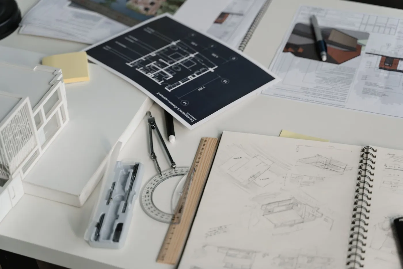
A drawing package should answer practical questions: where equipment goes, how it connects, what dimensions matter and how it can be maintained. Different project stages need different information.
02 / STEP BY STEP
A practical sequence.
- 01
Start with reliable inputs
Collect architectural backgrounds, measurements, equipment schedules and the intended scope.
- 02
Develop the arrangement
Place equipment and routes, showing the relationships that matter for the installation.
- 03
Coordinate interfaces
Review space for ducts, pipes, structure, ceilings, access and other building services.
- 04
Issue controlled revisions
Track comments and changes so the team can identify the current agreed information.
03 / LOOK A LITTLE CLOSER
The details that matter.
What 2D drawings do well
Plans, elevations, sections and details communicate dimensions and installation intent. They can be practical deliverables for focused repairs, replacements and small works.
What a Revit model adds
A model can help teams view equipment and services in three dimensions and coordinate spatial relationships. Its usefulness depends on the information modelled and the agreed scope.
Design drawings versus as-built records
Design drawings describe intended work. As-built records should reflect verified installed conditions. Site changes and measurements must be captured before treating drawings as an accurate record.
04 / AT A GLANCE
Keep these distinctions clear.
| Deliverable | Useful view | What it should clarify |
|---|---|---|
| Plan | Layout from above | Equipment locations, duct or pipe routes and dimensions. |
| Elevation / section | Vertical relationships | Levels, clearances, ceiling interfaces and connection heights. |
| Installation detail | A specific connection or assembly | Supports, fittings, insulation and access requirements. |
| Coordinated model | Three-dimensional relationships | Spatial review, coordination and agreed model information. |
THE KEY TAKEAWAY
Agree the file formats, drawing scale, revision process and level of detail before starting. “A drawing” can mean very different deliverables.
05 / COMMON QUESTIONS
Good questions to ask.
Do drawings replace a site survey?
No. Existing conditions must be confirmed to the level needed for the proposed work.
Does a 3D model guarantee installation will fit?
No. Coordination depends on accurate inputs, the modelled scope and verification of actual site conditions.
This guide explains typical arrangements. Equipment selection, technical settings and repair procedures must follow the actual system design and manufacturer’s instructions.